Technical paper by Chuck Cowlagi
Loading of liquid cargo into ships is a common operation carried out routinely throughout the world.
Extra caution is needed when handling oils of vegetable origin as these tend to undergo changes like rancidification, formation of sludge, change of viscosity etc. Therefore, it is necessary to empty the product from the discharge pipeline – especially when it is long.
On some old installations, where Progressing Cavity pumps were used in Palm Oil industry – it was an easy job to empty the discharge line. All that one had to do was to keep the suction and discharge valves fully open and start the pump in reverse direction. To make the operation effective, the loading line should have a slope towards the pump. The final section of the steel pipeline was always connected to a flexible hose or hoses through a discharge manifold.
To cater the larger demand and higher pumping rates, PC pumps were replaced by all- metal Twin screw pumps. Ability of pumps to empty the discharge line was forgotten. After installing the pumps, it was realized that the pumps were non-reversible!
Question: How to empty a 10” discharge line over 1 km long?
Installing a separate pump – specifically for emptying the line. Direction of rotation remaining same, but the position of suction and discharge ports suitably connected. This was a costly option- new pump, motor, control panel and of course changes in the piping plus the time required to modify. This idea was dropped.
Option No 2: Use a smaller portable pump and tap the discharge line near the pump to empty the line. This was even tried out for a while but needed operators to oversee the process. Time required to pump out the entire content was another factor that went against using this method.
Third option, suggested by the author during a site visit, was to modify the existing pipeline in such a way that with minimum changes the same pump could be used for loading a ship as well as emptying the line after ship loading operations were over.
This solution needed minimum changes and extra material – 2 Nos valves being the major extra material apart from a few flanges and pipe pieces and bends etc.
 When the modifications were completed, customer also realized additional benefits:
- the newly installed valve (V4) can be used for regulating the flow especially towards the end of loading operation.
- During intermittent operation – loading a next vessel after loading one- the pipeline would be full of oil: starting a pump under such condition caused additional backpressure. When trying to move a stagnant liquid in a pipeline- there will be an additional resistance apart from the pressure drop due to friction alone. Keeping V4 in open condition during the start-up- eased the load on the pump. Slowly closing the valve established full flow in the line. In short – the valve acted like soft starter!
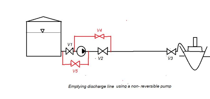
In the illustration, the red lines denote the modification carried out.
- During loading: Valves V1, V2 and V3 are fully open.
- During reverse operation: V1 and V2 are closed, V 3 is open. V4 and V5 are OPEN.
For loading another vessel, immediately after completion of one operation, valve V5 was closed. All other valves fully open. After starting the pump, valve V4 to be closed slowly but fully. This was to ensure smooth operation without any sudden changes and shock loading of pump/motor.
Initially it was a manually controlled operation but later converted to fully remote-controlled operation using motorized valve actuators, flow direction sensors etc.
Similar logic will also apply to pumping installations using centrifugal pumps which are also non- reversible.


