When VFDs – Variable Frequency Drive – made their appearance about 50 years ago, it was considered a fascinating invention. Over the years VFDs have seen many changes and it has become a reliable equipment for speed control in different ways.
In the enthusiasm to sell, VFDs were offered as a substitute for a mechanical /hydraulic speed variators. (speed reducers/ speed increasers – rolled in one). Advantage was tremendous -no mechanical equipment to maintain, power savings, soft start and smooth acceleration.
Every equipment has its own niche area of application. Stepping out of this without in depth study of driven equipment’s speed -torque requirement leads to failures and a needless bad reputation to the equipment itself.
Centrifugal pumps constitute the largest number among pumps used in industry. Along with their cousins – centrifugal fans and blowers – they form a group that has benefited from VFD. Flow regulation and power savings – both in one stroke!
However, the story is quite different when VFD is applied to PD – positiv displacment – pumps.
Here is a case history of misapplied VFD which was subsequently replaced with a fixed ratio gearbox!
- User: a multinational lubricant manufacturer – lube oils and greases ,
- Location : India
- Application: Pumping of High viscosity additives in a lube oil blending plant. Drive for a 30 HP, 8 pole motor directly driving a Twin-Screw Pump. Speed variation between 720 to 360 rpm by VFD ,to handle a product viscosity ranging from 6000 to 17000 cSt
A smaller gear pump was replaced by a larger Twin Screw pump to enhance plant capacity. Pump manufacturer offered pump with a direct coupled 8 pole motor with VFD, eliminating speed reducing gear box. This pleased the customer – as it saved space and maintenance.
Operational speed range was selected as 360 to 400 rpm. Logic: 8 pole VFD compatible motor ( 50Hz) will deliver approx. 720 rpm. VFD will bring down the frequency to achieve 360 – 400 rpm speed range. Lower viscosity fluids could be handled at higher speeds if needed.
Motor & Pump were tested at Pump manufacture’s works as a unit at 720 rpm on VG 68 oil. Test went as smoothly as planned. VFD was directly purchased by client from a VFD supplier.
At plant site when the unit was put into operation – the motor tripped even before reaching the required speed. Manual rotation, lowering product viscosity be heating the additive, torque boost feature of VFD… everything in the manual was tried out without success. This included several visits of service engineers from Pump manufacturer – since pump was under warranty.
Meanwhile, customer had to reinstall the earlier gear pump assembly to keep the production going instead of no production at all.
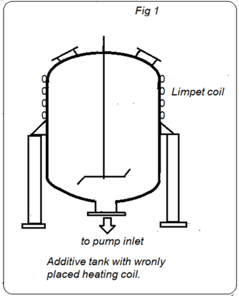
Observation at site: The sketch describes the installation. (see fig 1)
Inherent mistakes: the vessel holding the additive, approx. 6500 litres had a limpet coil on the top side. This would never heat the additive to the required temperature at pump intake! Hot oil circulation was intended as a means of keeping the additive temperature in the range of 50 to 55 °C. Obviously, the original design of the vessel may have been for a different purpose like preventing solidification of lighter layer of liquid. It could have never served for heating the contents of the vessel – in the first place no matter how long the heating process is kept ON.
Additive was at ambient temperature despite the circulation of hot oil through the limpet coil. High viscosity of the product meant high friction losses. Product to metal drag is even higher than between the layers of product.
Result: full dia of pipe would never be available for liquid movement – only the centre portion of the pipe was serving as effective conduit! Pressure drop was high as indicated by the readings on a compound gauge: high vacuum at pump suction despite a positive with 2 m of liquid column – when pump shaft turned a few rotations before causing motor to trip.
Starting torque of pump with high viscous medium is much higher than in lube oil medium. When testing in lube oil this fact can’t be noticed.
Motor operating with VFD delivers lower power although the full torque is available at speeds less than the rated speed of motor.
Drive motor rating 22 kW @ 720 rpm, against actual power requirement of 11kW. Despite this, the pump could not be operated. Points to note: a 30 HP motor will produce only 15 HP output when frequency is reduced from 50 to 25 Hz since Torque is constant during 0 to 50 Hz operation.
VFD briefly offers same Starting Torque as a DOL start would with increased voltage at reduced frequency. This is available for just 2 seconds.
Pump could be rotated by hand with a wrench (300 Nm), hence starting with a motor was not doubted. There is a negative margin (295 vs 291 Nm) on Torque when using a 30 HP, 8 pole motor with VFD!
Additive at ambient temp (30 ⁰C) has higher viscosity resulting in higher torque requirement by pump.
Solution offered:
- Replace the existing motor by a 15 kW, 4 pole motor with a 4:1 ratio speed reducer to achieve 360 rpm without VFD.
At first, this looked strange but on explaining the facts and admitting the fact the drive selection was flawed, customer agreed to accept the change with no commercial implications.
Accordingly, the entire pump+ motor assembly was sent to manufacturer located about 200 km away. New baseplate, coupling, (4:1 ratio) gearbox with 15 kW, 4 pole motor were arranged to couple with the same pump.
The completed unit was reinstalled at the plant at same location. When commissioned – the unit performed as per expectation with no glitch. The current consumption being well below the rated current of the motor. The test was continued till completion of the batch. Satisfied, customer signed the service report but desired to know what the “gimmick”!
The explanation is simple:
- Pump starting torque with 6000 cSt fluid: approx. 300 Nm. … (Ref A 6)
- Operating torque for duty condition : 291 Nm , Power needed at 360 rpm= 11 kW
- Motor Torque (rated) ; ( 30 HP , 720 rpm) = 291 Nm (Ref A 3)
- Ratio: Tst/Tr = 2 for DOL starting or with Torque Boost Feature on.
- Available torque for Pump starting: 291x 2 = 582 Nm with 30 HP, 8 pole motor with VFD ..(Ref A 7)
- Since the Motor with VFD start is much like a soft starter – picking up speed gradually. During the period from start to reach full speed, the torque remains constant but not the power.
- Power = Torque x Speed/ constant, in SI units, Power – kW, Torque – Nm, Speed -1/s. Numerical value of constant is 9550.
- High current drawn during the acceleration period caused motor to trip.
- What happens when a 15 kW (20HP) motor with 4:1 speed reducer replaced the 22 kW drive? The torque of a 15 kW, 4 pole motor is only 98 Nm- far less that what is needed. However, the speed reducer acts as a torque multiplier in the same ratio: 98 x 4 = 392 Nm! …( Ref B 3)
- This is the rated torque value. On DOL start this will be 2 times higher I,e, = 392 x 2 = 784 Nm!! …. …(Ref B 7)
If the process parameters are met by the pump – any customer is happy. But it is not necessary to go through such experience to learn a lesson!
To facilitate pumping, two suggestions were made:
- Place the limpet coil at the lower section of the vessel. The entire mass of additives will be heated by convection. (The limpet coils at the upper section made no sense – at least for this application)
- Provide a full flow by- pass across the suction and discharge ports with a valve in between. Keep the valve fully open during starting and then gradually close it to get full flow. This will be especially useful if liquid viscosity is higher than expected.
Curiosity does not die: why did the manufacturer suggest a direct drive with VFD instead of well tested Geared motor drive for low speed operations?
The engineer who had made the pump selection had already left the company but when contacted said:” it was customer’s request to avoid gearbox in the proposal “!
After all this episode was over, we asked the customer if this was true. He said “Yes”! Honest customer – a rare commodity these days!
| Ref. | Motor 30 HP / 8 pole with VFD
(A) |
Motor 20 HP/4 pole with 4:1 ratio reducer (B) | |
| 1 | Power at rated speed (720 rpm) HP | 30 | 20 |
| 2 | Power required at 360 rpm, HP | 15 | 20 |
| 3 | Drive Torque @ 360 rpm | 291 Nm | 392 Nm |
| 4 | Torque required by Pump at rated speed (360 rpm) | 295 Nm | 295 Nm |
| 5 | Pump starting Torque
Without additive |
100 Nm | 100 Nm |
| 6 | Pump starting torque with additive | 300 Nm | 300 Nm |
| 7 | Drive starting torque | 582 Nm
With Torque Boost feature |
784 Nm |
Points to note: a 30 HP motor will produce only 15 HP output when frequency is reduced from 50 to 25 Hz since Torque is constant during 0 to 50 Hz operation.
VFD briefly offers same Starting Torque as a DOL start would with increased voltage at reduced frequency. This is available for just 2 seconds.
Pump shaft could be rotated by hand with a wrench (300 Nm), hence starting with a motor was not doubted. There is a negative margin (295 vs 291 Nm) on Torque when using a 30 HP, 8 pole motor with VFD!
Additive at ambient temp (30 ⁰C) has higher viscosity resulting in higher torque requirement by pump.
Lessons learnt:
- VFD is not a substitute for a speed reducer gear box . Gear box acts as a torque Multiplier – VFD can only ensure constant torque equal to motor rated torque.
- The Power output of a motor will reduce in direct proportion to speed or Frequency when a VFD is used.
- If specified viscosity is lower than actual – there will be problems!
For more information contact cowlagi@polydrill.com

")


