Account for consequences of acceleration head in designing pump pipework
Technical Paper by Simon Bradshaw, Director Engineering Pumps Americas, Circor
Anyone designing a pump and piping system with high vapor pressure and a long suction pipe should spend some time thinking about the net positive suction head available (NPSHA) margin they need for their service. And that means more than just consulting industry standards and calling it a day. Otherwise you may end up like one facility handling light hydrocarbons I learned of. They did not consider the consequences of acceleration head – and paid for it with significant equipment problems that ended up losing them millions of dollars a day in lost revenue.
Industry standard for NPSH margin
Currently the “go to” industry standard for NPSHA margin is Hydraulic Institute Standard 9.6.1 (2012) [1]. For pipework design, the Hydraulic Institute Standard 9.6.6 (2016) [2] provides guidance on how to design pump suction and discharge piping correctly in order to avoid pump problems. The standards have a lot of useful, actionable information, but they do not provide enough design guidance to deal with the consequences of fluid acceleration.
Take the example of a large project that was pumping a volatile hydrocarbon. The fluid was stored in an elevated drum that fed up to three single stage centrifugal pumps in parallel through a common suction header. Design NPSH margin (NPSHA-NPSHR) was around 5 meters.
Two problems doomed the original design (which fully complied with standards found in HI 9.6.1 and 9.6.6.) First of all, the suction pipework between the elevated drum and the pumps was around 90 meters (295 feet) long and equivalent to around 200 meters (656 feet) pipe length, when losses from such fittings as valves and bends were considered. Secondly, the pumps were motor-driven with a simple direct online (DOL) start, like most pumps in the oil and gas industry. This means there was no soft start or variable frequency drive (VFD).
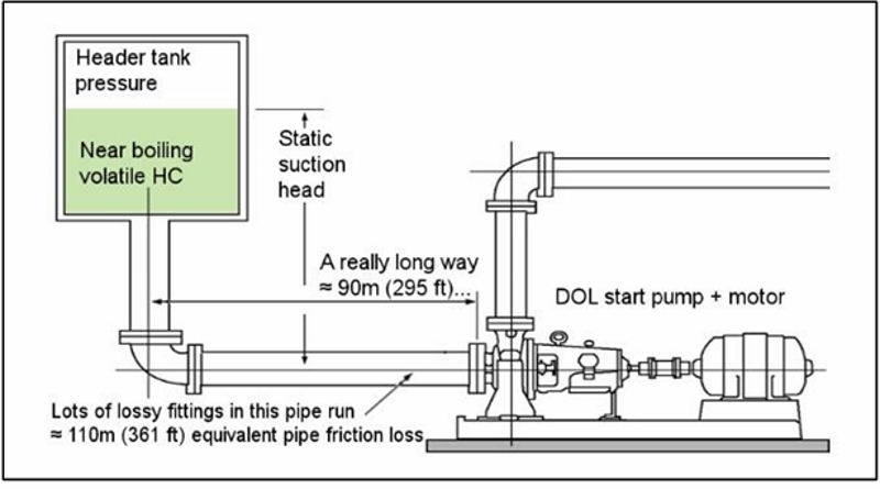
Figure 1 shows a generalization of the system layout.
Understanding the role acceleration plays
So let’s discuss why the original design was doomed. Most of the time we think of flow into a centrifugal pump as a smooth steady state event. (Actually, the cavitation in a centrifugal pump is inherently transient, not steady state, but for our purposes we can consider it to be a steady state.)
However, during startup, fluid must accelerate from standstill to a velocity that achieves the rated flowrate. Newton’s 2nd law states that exerting a certain force (F) on a given mass (m) will yield a resulting acceleration (a), in accordance with the equation F = ma.
Extrapolating this concept into something usable for starting a pump, we know how quickly the flow needs to accelerate, and we know the mass of the fluid, so we can compute what force is required. That force has to be supplied by the pressure acting on the fluid – meaning that some of the available NPSHA is used to provide the necessary force to accelerate the fluid. The equation that illustrates the process is H = LΔV/gt [3], where:
- H = required acceleration head in meters
- L = length of suction pipe in meters
- ΔV = the change in velocity required in meters per second (m/s)
- g = acceleration due to gravity (9.81 m/s2)
- t = time in seconds
Using the project values with a single pump DOL start, we get:
H = 90 * 1.5 / (9.81 * 0.5) = 27.5 m
Do you spot the magnitude of the problem the facility faced? We have limited NPSHA, and a large mass of fluid, due to the long length of inlet pipe and pumps that are starting very quickly, making t small (around 0.5 seconds). The required acceleration head is 27.5 meters, while the NPSHA -NPSHR on the project was only about 5 meters, when considering fluid heating and friction losses in the suction piping and fittings. This meant that the pump could not start normally without going into full cavitation (complete head breakdown) and losing prime.
Worse, even if the pump could somehow be started while retaining prime, it was difficult for the pump to handle any increases in plant flow demand. This is because the flow change had to occur slowly enough to allow the fluid in the suction piping to accelerate to the new higher velocity without the cavitation in the pump becoming excessive. The situation proved to be quite expensive to the owners of the $1+ billion plant.
Stephen Shakeshaft, a professional rotating equipment and mechanical engineer who first identified the problem and who served as a consulting engineer for startup of the facility, described the plant operators as “hanging on to correct operations by their fingernails, taking flow to the edge – with no room for any error.” [4]
In the end, he worked out a solution by radically shortening the suction piping runs. He also had to develop a fairly complex control logic involving the minimum flow control valve and main flow control valves to avoid a fault condition occurring. It was quite a challenge when you consider the number of possible operating conditions.
The startup and load following sequence looked something like this:
- Start the pump dead-headed (zero flow) and quickly verify the pump is at 100 percent speed. (The pump needs to be confirmed as fully vented prior to starting for this to be successful).
- Slowly open the minimum flow bypass line up to the pump minimum continuous stable flow (MCSF) over a period of 8 seconds.
- Verify that minimum flow was achieved.
- Slowly ramp the flowrate in the main discharge line over a period of 12 seconds until the demand flow is reached.
- If a higher flow is commanded, slowly ramp the flowrate in the main discharge line at the same rate as shown in Step 4.
Keep in mind that the control parameters had to be established by extensive testing with one pump. Then they had to do the same testing and tuning all over again with two and three pumps running in parallel.
Another way of figuring in acceleration head
It is clear that Hydraulic Institute Standards 9.6.1 and 9.6.6 currently do not adequately consider the acceleration head. This is a missed opportunity, since acceleration head is well known to those working with reciprocating pumps. For them, fluid is constantly accelerating and decelerating. Hydraulic Institute Standards 6.1-6.5 (2015) [5] design guidelines deal with these issues.
If Hydraulic Institute Standards 9.6.1 and 9.6.6 had warned the contractor about the consequences of acceleration head, the pipework and control system could have been optimized and issues resolved at the design stage well before any concrete was poured or welds made.
Hopefully this lesson can be included at the next update of the standards, but until then, those designing a pumping system with high vapor pressure fluids and long suction piping runs should exercise precautions. It is not an everyday situation, but when it happens it can be fairly catastrophic. At the facility in question, operators had to redesign the piping system, make extensive process control modifications, and delay startup, losing out on about $3 million a day in revenue.
References and Sources
- Rotodynamic Pumps Guideline for NPSH Margin (ANSI/HI 9.6.1-2017 – Secure PDF), https://estore.pumps.org/Standards/Rotodynamic/NPSHPDF.aspx, retrieved 11/1/2018.
- Rotodynamic Pumps for Pump Piping (ANSI/HI 9.6.6-2016 – Secure PDF), https://estore.pumps.org/Standards/Rotodynamic/PipingPDF.aspx, retrieved 11/1/2018.
- Acceleration Head, Terry Henshaw, Pumps and Systems, December 17, 2011, https://www.pumpsandsystems.com/topics/pumps/centrifugal-pumps/acceleration-head, retrieved 11/19/18.
- Stephen Shakeshaft, professional rotating equipment and mechanical engineer, who served as a consulting engineer for startup of the facility. Find him at https://www.linkedin.com/in/rotatingequipmentengineer/
- Reciprocating Pumps (ANSI/HI 6.1-6.5-2015 – Secure PDF), https://estore.pumps.org/Standards/Reciprocating/PumpsPDF.aspx, retrieved 11/1/2018.


