Technical paper by Manuel Monroy, Field Engineer at Sulzer
High energy pumps are used throughout many industries, one of those industries being the petrochemical industry. As important assets, they are designed to provide reliability while maintaining their designed efficiency for many years. Whilst pump designers have somewhat of a free hand when designing pumps, some design features for the petrochemical market must meet the requirements of API 610. In the last 30 years API 610 has evolved from 5th edition to 12th Edition. Sulzer has both the expertise and engineering facilities to take those vintage pumps in to their service center designed many years ago to API 610 5TH Edition and return them back to the customer as API 610 12TH Edition. This paper explains a range of improvements that can be implemented, taking the Pacific JTC multi-stage centrifugal pump as an example.
The dynamic challenges in the oil and gas industry create a constant demand for innovative solutions to allow longer, trouble free, operating intervals. Pumps designed for a specific service many years ago may not be operating now at the conditions for which they were designed. At Sulzer, the mindset is to offer repair solutions to customers’ equipment with the latest upgrades available in the industry which improve reliability and efficiency.
From 1958 to 1989 the Pacific JTC multistage diffuser pump was introduced to the petroleum industry, as well as the power industry, both fossil and nuclear.
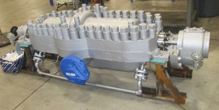
The JTC is a horizontal split case diffuser style pump with a back to back impeller configuration. Most split case pumps are of the volute style with hydraulic passageways cast throughout the casing halves. The casing of the JTC is a much simpler design, shown on picture 1 below. The casing has one major diameter that radially locates all the inter-covers. The inter-covers, which are sealed on their outside diameter with the casing, to prevent inter-stage leakage, contain the diffuser and return guide vanes and transfers the fluid from the discharge of one impeller to the inlet of the next impeller. The bolt pattern used to bolt the two halves together does not have to weave around volute passageways, making it easier to achieve uniform loading on the split line required for sealing purposes.
Other pumps with similar designs are the IR CNTA, IR HMTA and the Worthington WT. The JTC and CNTA pumps are designed with opposed impeller configuration compared to the IR HMTA and Worthington WT, which are designed with impellers in tandem. The opposed impeller configuration on the JTC and CNTA balances the axial thrust created by the impellers. Tandem impeller configurations create a very high inboard thrust, balancing this thrust requires a more in depth design compared to the opposed impeller design.
Most of the pumps shipped many years ago were shipped with packing seals. The JTC has a small shaft diameter and the gland packing is crucial. Not just for sealing the product from leaking to the atmosphere, but it also acts as a bearing, consequently aiding both center and throttle bushings in maintaining rotor stability during operation. The use of gland packing to seal the pump’s stuffing box often requires adjustment in the field which is a continuing maintenance headache for many operators.
The introduction of the mechanical seal and its superior sealing technology increased the demand for aftermarket upgrades that paved the way for retrofitted pumps and new industry standards.
Retrofitted JTC pumps are now commonly equipped with mechanical seals eliminating fugitive emissions, a major driving force behind this was the release of API-610 7th edition which standardized on mechanical seals and the stuffing box requirements. However, the modification of existing pumps with packed stuffing boxes to mechanical seals did not come without problems. With the addition of mechanical seals, mounted on a slender shaft, the pumps rotor dynamic behavior changed. This change led to the accelerated wear of the close running clearances, an increase in vibration, further opening up of the clearances and the vicious cycle continued until the pump could no longer perform its function both mechanically due to high vibration and hydraulically due to internal leakage. The change in rotor dynamic behavior resulted in the creation of innovative solutions to maintain and increase the mean time between repairs (MTBR) of the JTC pump.
Recently, during a routine turnaround, a chemical plant located in Pasadena, TX., took the opportunity to overhaul their JTC pumps with a view to improving both bearing and seal life. Sulzer’s Houston Service Center provided engineering support and repair solutions to increase the MTBR. The pump was a typical JTC small shaft design with mechanical seals, originally designed for packing.
The customer’s supplied JTC pumps arrived at the service center with significant damage. The customer noted that the pumps were experiencing constant seal and bearing failures. Excessive wash-out was found on the casing inner diameter where an O-ring provided inter-stage sealing between the inter-covers and casing diameter. Sulzer’s quality (QA) team also found the case split line flatness out of tolerance. Typical wear was found throughout the rotor wear components from years of service.
To meet the customer’s expectations, Sulzer’s Houston Service Center engineering team took on the task of providing a solution to increase the MTBR of their existing pump. Equipped with state-of-the-art 3-dimensional laser scanners and API experienced engineers, the service center began by completely reverse engineering the original JTC pump. After a design review, a proposal to repair and retrofit the pump was created and presented to the customer.
Sulzer had two main objectives, repair the casing damage to original design standards and provide a solution to eliminate the accelerated wear of the close running internal clearances.
Casing repair
To restore a pump case inner fits and bring them back to original equipment manufacturer (OEM) tolerances, boring of such fits is practiced in the industry. When boring a pump case, alignment of the pump case to its center line is the most important step in the machining process and of the entire repair. It was important to strategize and properly engineer and execute the appropriate repair process that would allow the restoration of the pump’s critical case fits.
The stacked diffuser design on the JTC required multi-point inspection on all internal mating faces to ensure parallelism and concentricity met Sulzer’s standards. To correct out of tolerance runout, Sulzer engineered and manufactured special tooling to properly correct excessive runout on critical mating surfaces.
To remove the wash-out and runout found on the pump case, it was put through multiple machining phases. The case split line was planed on one of Sulzer’s planer mill. The case bore fits were also machined to the required dimensions maintaining tight tolerances and concentricity to the case split line. Finally, the case inner walls were machined, with the case halves torqued, to ensure parallelism between both inner walls that axially locate the inner element located 40 inches apart.
Rotor upgrade
When addressing accelerated wear in the close running clearances of the JTC pump there are two typical improvement options.
- Provide non-metallic composite materials for the wearing parts and reduce the running clearances
- Upgrade the rotor from a spacer sleeve designed rotor to a split ring designed rotor

On this occasion Sulzer implemented non-metallic materials for all stationary wear components, such as eye and hub rings, throttle bushing and center bushing. Distinct pressure distribution seen on the throttle bushings and center bushing required additional design calculations and ultimately resulted in the implementation of the perforated insert (Perf-Seal) design shown on picture 2. A Perf-Seal insert has radially drilled holes throughout the non-metallic insert and these prevent differential pressure from extruding the insert from the metal holder.
Non-metallic composite materials are capable of withstanding temperatures of up to 500 °F (260 °C). They are widely used in the pump industry for wear ring components, bushings and inserts. The major benefit of these composites is the ability to withstand occasional dry running. If there is a pump failure then the non-metallic rings become the sacrificial pieces, all other components can be repaired and re-used. The composites also allow for reduced running clearances, which provide improved stiffness and damping along the length of the rotor improving rotor stability and an increase in pump efficiency. It should be noted that reliability is the main reason for converting to the non-metallic rings, efficiency is secondary.
With the case fully restored and with new wear parts machined at the service center, the pump was ready for assembly. The impellers were individually balanced and the assembled rotor check balanced. The loose design fit between the impellers and shaft required critical runout inspection during assembly. Finally, during the rotor stack up, all impellers and diffusers were set to their corresponding running position to ensure the impellers’ and diffusers’ hydraulic passageways were properly aligned.
Further upgrades available
Due to time constraints, the upgrade of the rotor from sleeve to split ring design could not be accommodated. The existing spacer sleeve design with two locknuts at each end designed to lock the rotor together is known to create run-out problems both at assembly and during operation. The rotor can be further upgraded to a split ring designed rotor. This eliminates the spacer sleeves between the impellers and allows the impeller thrust at each individual stage to be transferred to the pump shaft via the split ring. With the elimination of the spacer sleeves, the shaft diameter can be increased in some cases by 0.5 – 0.75 inches (12 – 19 mm) through the impeller section of the pump shaft. This also allows an interference fit between the shaft and impeller, reducing runout on the impeller wear surfaces and providing the ability to balance to a much tighter balance criteria. The pump when upgraded in this fashion can meet the vibration requirement of the latest API 610 standards.
If the impellers are weldable then back hubs can be welded to the existing impellers, allowing the existing impellers to be re-used. If the original impellers are cast iron they must be replaced.
For components with complex geometry, such as impellers and case diffusers, Sulzer used Crea Form® scanners to allow rapid 3D modeling of customer supplied equipment. The 3D scanner is a powerful tool widely used in the industry to properly enable the manufacturing of cast components. This allows Sulzer to provide replacement impellers meeting the existing hydraulic and envelope requirements. For changes in pump performance, Sulzer engineering can analyze existing performance data and can adjust the hydraulic components accordingly to meet new process conditions. During time restricted turnarounds where a new rotor requisition is not feasible, Sulzer engineering can perform a mechanical review of the existing rotor and advise on necessary rotor changes needed to improve bearing life and improve rotor stability.
Centering shim
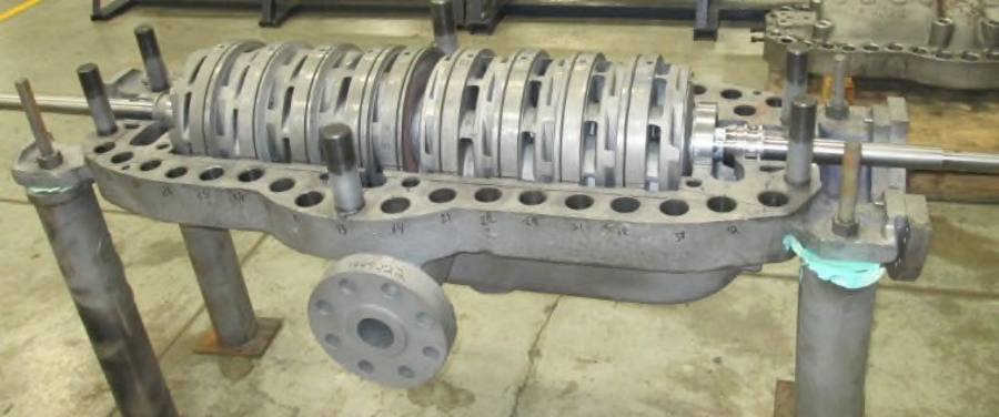
The original rotor design on the JTC includes a centering shim, which ensures the rotor fits tightly into the pump casing by shimming the center stage casings accordingly. The disadvantage of having a centering shim in the middle of the rotor is having to disassemble half of the rotor to properly adjust the shim should the rotor not fit into the casing with the proper axial clearance, see an example of in case rotor assembly detailed on picture 3. An upgrade is available that removes the center shims and moves it to the front of the 1st stage diffuser. By providing a laminated shim, quick adjustments can be made to the rotor axial length for final assembly. This upgrade is ideal for quick bundle swaps and has the potential to reduce lead-time on repairs.
Bearing and seal modifications
To increase bearing life, bearing housing upgrades can also be achieved by retrofitting the existing cast iron housings with Sulzer’s carbon steel ball-ball or ball-sleeve arrangement bearing housings. These are designed with integral fins that dissipate heat and can be equipped with a wide variety of instrumentation connections such as resistance temperature detectors (RTDs), bearing coolers and vibration probes.
In some cases, new air-cooled bearing housings may allow for the removal of existing water-cooled housings and the associated piping.
Sulzer’s bearing housing assemblies can increase the bearing sizes for ball-ball arrangements or implement shorter length/diameter ratio (L/D) journal bearings for sleeve-ball arrangements. The housings are also equipped with Inpro® isolators to protect the housing internals from contaminants. Engineers can custom design the bearing housing mating flanges to adapt to the current pump case bolt pattern and minimize any case re-work.
Meeting new standards
The petrochemical industry has a wide range of split case diffuser pumps similar to the JTC, like the IR CNTA, IR HMTA and Worthington WT. Although, rotor configurations between them vary, many of the reliability challenges remain the same among these product lines. Instead of scrapping an outdated split case diffuser pump, some of the JTC upgrades detailed above may be the practical solution to restore and improve pump performance while upgrading to API’s 610 12th edition and ultimately increase MTBR.
At Sulzer, the goal is to provide pump reliability solutions through engineering and in-house manufacturing. Sulzer is proud to provide pump repairs and retrofits on all types of pumps (Sulzer and non-Sulzer), taking on the challenge to upgrade customers’ equipment that meet new industry standards.


